
Get to know more about the project below
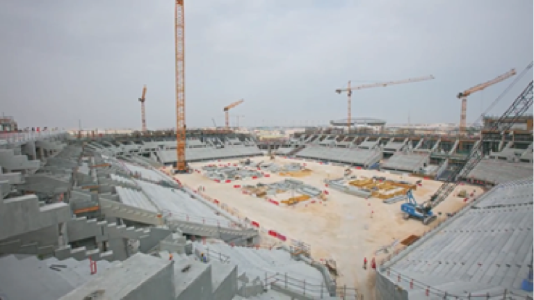
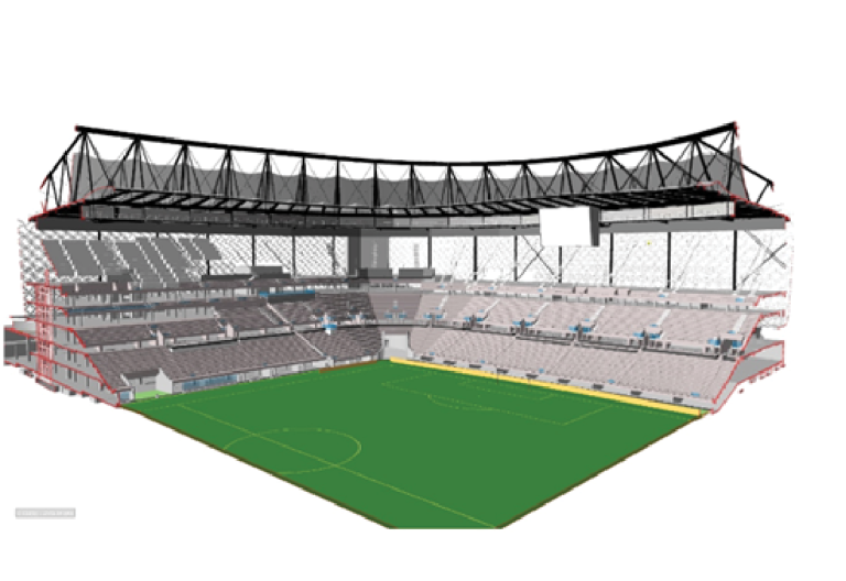
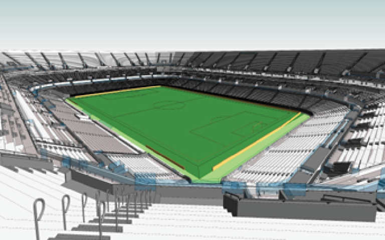
Our BIM team from Pan Gulf Technologies delivered this magnificent football stadium project with a seating capacity of 40,000 emerged as an iconic venue during the thrilling games of the highly anticipated 2022 FIFA World Cup. This architectural marvel stands tall, showcasing a perfect blend of strength and elegance with its concrete and steel structure. Embracing sustainability, the stadium incorporates state-of-the-art cooling systems that ensure a comfortable environment regardless of the season. Providing parking for over 6,000 cars and 350 buses, it guarantees convenience and accessibility for all fans.
Qatar
40,000.
Revit 2016, Navisworks Manage 2016, Solbri, AutoCAD 2016
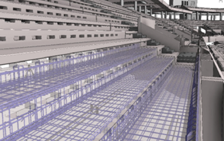
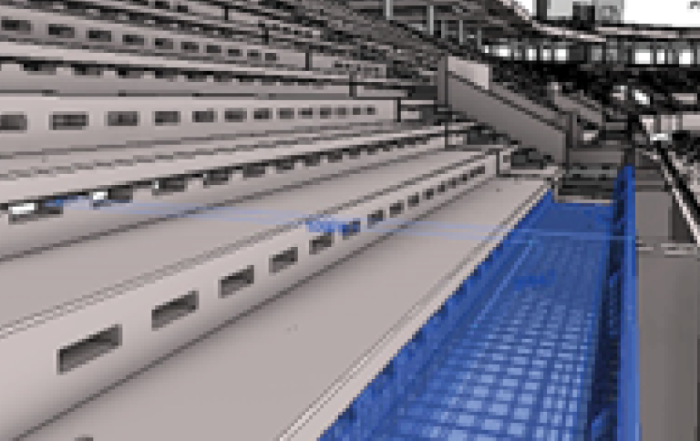
Revit model creation @ LOD 400 from IFC(Issued for Construction) drawings.
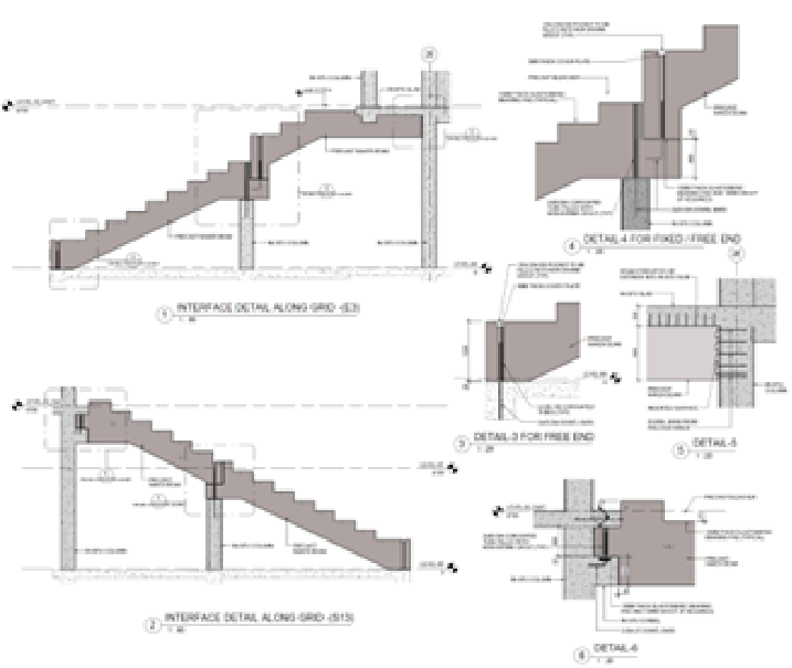
• The primary scope of work for the project included creation of BIM Model for all precast elements (Bleachers, Rakers, Staircases,
Slabs) of the Stadium at LOD 400.
• To support the General Contractor’s & Sub-contractor’s BIM requirements for all project stakeholders.
• Clash Detection, Coordination & Resolution between relevant disciplines.
• Creating detailed concrete shop drawings for all precast elements of the stadium.
• 4D Scheduling by mapping the Project Timeline/Schedule with the Model.
• Quantification for Estimation
• Cobie Compliance as required by the Client
• As-Built updating based on Site data.
Stage 1: Revit model of LOD 400 from Issued for Construction Drawings. Models were created for Slabs, Raker Beams, Bleachers,
Vomitory Walls, Vomitory Steps, Bleacher Steps, Stair, Landing and Precast Walls.
Stage 2: Inter & Intra discipline Coordination, Escalation of RFIs (Request for Information)/TQs (Technical Queries) for
Constructability/Clash issue. Updating Model with changes resulting from Design changes & RFI responses.
Stage 3: Shop/production Drawing Creation. Team Created 1000+ Production drawings for all precast elements (4000+ elements).
Managing production flow by providing production schedule and site progress.
Stage 4: Inserting Cobie parameters based on Client’s requirement.
Stage 5: Reconciling data from site and production team and updating LOD 400 model to LOD500 as-built Model.
Get in touch with our
Expert’s Today!